major function
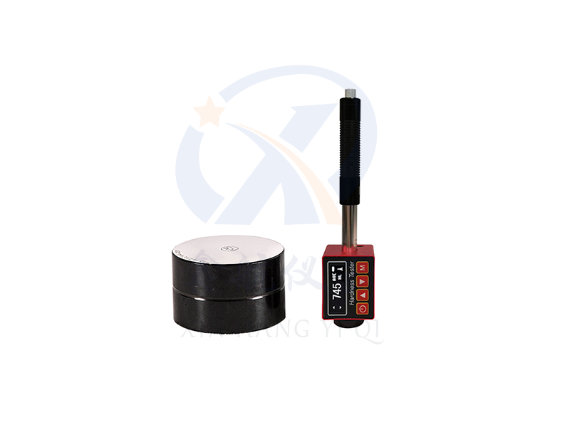
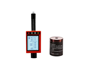
According to the principle of Leeb hardness measurement, the Leeb measurement interface will be displayed upon startup.
Menu style operation, rich and intuitive information.
High brightness LED backlight is convenient for use in dimly lit environments.
Automatic sleep, automatic shutdown and other power-saving functions, with low-power design.
Lithium ion battery charging, can work continuously for 10 hours.
Applicable materials
Steel and cast steel, alloy tool steel, stainless steel, gray cast iron, ductile iron, cast aluminum alloy, copper zinc alloy (brass), copper tin alloy (bronze), pure copper, forged steel.
Main uses
1. Installed mechanical or permanently assembled components
2. Mold cavity, heavy workpiece
3. Failure analysis of pressure vessels, steam turbine generators and their equipment
4. Measuring workpieces, bearings, and other parts with limited space
5. Material differentiation in metal material warehouses and inspection of multiple measurement locations for large workpieces on a large scale
6. When testing the hardness of bearings, attention should be paid to their bearing diameter. If the diameter is too small, an irregular support ring should be selected
Test scope
|
project
|
XH-180
|
|
Indication error
|
±0.3% (HL=800/±2HL)
|
|
Hardness value
|
HL/HRC/HRB/HB/HV/HS/HRA/σB(Rm)
|
|
Recognizable impact device type
|
Dtype
|
|
Measuring angles
|
Full angle
|
|
storage capacity
|
300Data
|
|
statistics
|
Average, maximum, minimum
|
|
source
|
3.7VLithium ion rechargeable batteries,Can work continuously40hour
|
|
Instrument volume
|
148X44X22(Mm)
|
|
Net weight
|
110g
|
|
standard
|
accord withGB/T 17394-1998,ASTM A956standard
|
|
Impact deviceD HLD:170-960Customizable hardness values that are not marked
|
|
Test materials/Hardness system
|
HRC
|
HRB
|
HB
|
HV
|
HS
|
HRA
|
σB (N/mm²)
|
|
Steel and cast steel
|
20.0-67.9
|
59.6-99.5
|
80-647
|
80-940
|
32.5-99.5
|
30-88
|
375-1710
|
|
Alloy tool steel
|
20.5-67.1
|
|
|
80-898
|
|
|
1170-2639
|
|
Stainless steel
|
19.6-62.4
|
46.5-101.7
|
85-655
|
85-802
|
|
|
740-1725
|
|
Gray cast iron
|
21-59
|
24-100
|
93-334
|
90-698
|
|
|
|
|
Ductile iron
|
21-60
|
24-100
|
131-387
|
96-724
|
|
|
|
|
Cast aluminum
|
|
24-85
|
30-159
|
75-227
|
|
|
|
|
Copper zinc alloy (brass)
|
|
13.5-95.3
|
40-173
|
|
|
|
|
|
Copper tin alloy (bronze)
|
|
14-100
|
60-290
|
|
|
|
|
|
Pure copper
|
|
14-100
|
45-315
|
|
|
|
|
|
Forged steel
|
|
|
142-651
|
|
|
|
|
Note: When using a Leeb hardness tester for measurement, the tested workpiece needs to be suitable for the corresponding testing conditions, mainly due to three requirements: the weight of the workpiece should not be less than2KG, with a minimum thickness of10mmThe surface roughness is not greater than1.6umWhen the above conditions are not suitable, stable support or dense coupling is required!
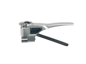
Impact device
|
Impact device
|
DC/D(Standard configuration)/DL/DS
|
D 15
|
C
|
G
|
|
Impact energy
|
11mj
|
11mj
|
2.7mj
|
90mj
|
|
Impact mass
|
5.5/5.5/7.2/5.5 g
|
7.8 g
|
3.0 g
|
20 g
|
|
Ball hardness
|
1600 HV
|
1600 HV
|
1600 HV
|
1600 HV
|
|
Ball head diameter
|
3 mm
|
3 mm
|
3 mm
|
5 mm
|
|
Ball head material
|
Tungsten carbide
|
Tungsten carbide
|
Tungsten carbide
|
Tungsten carbide
|
|
Impact device diameter
|
20/20/6/20 mm
|
20 mm
|
20 mm
|
30 mm
|
|
Impact device length
|
86/147/202/138 mm
|
162 mm
|
141 mm
|
254 mm
|
|
Impact device weight
|
50/75/60/70 g
|
80 g
|
75 g
|
250 g
|
|
Upper limit of specimen hardness
|
940/940/950/940 HV
|
940 HV
|
1000 HV
|
650 HB
|
|
Average surface roughness of the specimenRa
|
1.6 µ m
|
1.6 µ m
|
0.4 µ m
|
6.3 µ m
|
|
Scope of application of impact device
|
DCType measurement inner hole or cylindrical cylinder;
DLMeasurement of slender and narrow grooves or holes;
DType is used for routine measurements;
DSOnline detection of type measurement pipeline (loading and releasing completed in one go)
|
D 15The contact surface is small and elongated, suitable for measuring grooves or recessed surfaces.
|
CLow impact force, minimal damage to the tested surface, no damage to the hardened layer, suitable for measuring small, lightweight components and surface hardened layers.
|
GMeasurement of large thickness and rough surface of castings and forgings.
|
Indication error and indication repeatability
|
Number
|
Impact device type
|
Standard Leeb hardness block hardness value
|
Indication error
|
Repeatability of indication values
|
|
1
|
D
|
760±30HLD
530±40HLD
|
±6 HLD
±10 HLD
|
6 HLD
10 HLD
|
The Leeb hardness tester meets the standard
1GB/T 17394.1-2014Leeb hardness test for metallic materials1Part: Test Methods
2GB/T 17394.2-2012Leeb hardness test for metallic materials2Section: Inspection and Calibration of Hardness Testers
3GB/T 17394.3-2012Leeb hardness test for metallic materials4Part: Calibration of Standard Hardness Blocks
4GB/T 17394.4-2014Leeb hardness test for metallic materials4Part: Standard Value Conversion Table
5Design basis standard: Technical conditions for Leeb hardness testerJB/T 9378-2001
Requirements for the surface of the tested sample
The surface condition of the sample should meet the relevant requirements in the testing range table.
The surface temperature of the sample should not be too high and should be less than 120 ℃.
The surface roughness of the sample should not be too large, otherwise it may cause measurement errors. The tested surface of the sample should show a metallic luster, and be flat, smooth, and free of oil stains.
● Requirements for sample weight: For heavy samples larger than 5kg, no support is required; During testing, specimens weighing 2-5kg, those with overhanging parts, and thin-walled specimens should be supported by objects to avoid deformation, bending, and movement caused by impact forces. For medium-sized specimens, place them on a flat and sturdy surface, and place them steadily without any shaking.
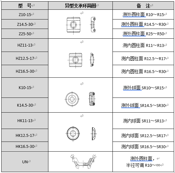
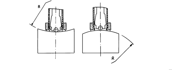
● Curved specimen: The test surface of the specimen is flat. When the curvature radius R of the tested surface is less than 30mm (D, DC, C, DL type impact devices) and less than 50mm (G type impact devices), small or irregular support rings should be used during testing.
The sample should have a corresponding thickness, and the small thickness of the sample should comply with the provisions of the impact device table.
For specimens with a surface hardening layer, the depth of the hardening layer should comply with the provisions of the impact device table.
● Coupling
1) For lightweight specimens, they need to be tightly coupled with a sturdy support body, and the two coupling surfaces need to be flat and smooth. The amount of coupling agent should not be too much, and the testing direction should be perpendicular to the coupling plane;
2) When the sample is a large-area plate, long rod, or bent part, even if the weight and thickness are large, it may still cause deformation and instability of the sample, resulting in inaccurate test values. Therefore, it should be firmly fixed or supported on the back of the test point.
The magnetic properties of the sample itself should be less than 30 Gauss
measuring method
Press the release button on the upper part of the impact device for testing. At this point, it is required that the specimen, impact device, and operator are all stable, and the direction of the force should pass through the axis of the impact device.
Each measuring part of the sample is generally tested five times. Data dispersion should not exceed ± of the average value15HL.
The distance between any two indentations or the distance between the middle of any indentation and the edge of the specimen should comply with the provisions in the table below.
For specific materials, in order to accurately convert the Leeb hardness value to other hardness values, comparative tests need to be conducted to obtain the corresponding conversion relationship. The method is to conduct tests on the same sample using a certified Leeb hardness tester and the corresponding hardness tester. For hardness values, measure uniformly distributed around three or more hardness indentations that need to be converted5Point at the Leeb hardness and use the average Leeb hardness value and the corresponding average hardness value as corresponding values to create a hardness comparison curve. The comparison curve should include at least three sets of corresponding data.
|
Impact device type
|
Distance between two indentations
(Mm)
|
The distance between the indentation point and the edge of the sample
(Mm)
|
|
D
|
3
|
5
|
Fault analysis and troubleshooting
|
Fault phenomenon
|
Cause analysis
|
Exclusion method
|
|
Not turning on
|
Depleted battery
|
Timely battery
|
|
Inaccurate measurement
|
Wear of the impact device ball head
|
Replace the ball head
|
|
Measurement deviation
|
Calibration value invalid
|
Recalibration
|
Maintenance and repair
1. Impact device
●After using it for 1000-2000 times, clean the catheter and impact body of the impact device with a nylon brush. When cleaning the catheter, first unscrew the support ring, then remove the impact body, rotate the nylon brush counterclockwise into the tube, pull it out to the bottom, repeat this process for 5 times, and then install the impact body and support ring;
●After use, the impact body should be released;
●Lubricants are strictly prohibited from being used inside the impact device.
2. Normal maintenance procedures
●When using standard Rockwell hardness blocks for calibration, the error is greater than2HRCAt this time, it may be due to wear and failure of the ball joint, and replacement of the ball joint or impact body should be considered.
●When there are other abnormal phenomena in the hardness tester, please do not disassemble or adjust the fixed assembly components. After filling out the warranty card, it should be handed over to our company's maintenance department to implement the warranty regulations.
Heterogeneity support ring (optional)